ECU
Engine Control Unit
Syrus 4G IoT Telematics Gateway has a built-in ECU interface, which allows the device to connect to a vehicle's CAN bus and read data.
General Overview
- The way it works is that you instruct the Syrus to read data at a certain speed for a particular protocol, for example read J1939 data at 250KHz from the PRIMARY CAN wires on the device.
- Once the corresponding wires are connected to the vehicle's CAN bus, the ECU will parse the parameters found in the corresponding parameter file inside the device.
- By default Syrus 4G comes loaded with a predefined list of common parameters, but this list is editable by the user, so they can expand or select only the parameters he/she wants.
- Once the parameters are being read you can use an application like SyrusJS to obtain the engine data and send it to an endpoint or create rules/trigger actions based on the values reported.
- You can also use the Syrus 4G to log data from the CAN bus and interpret any proprietary parameters found, provided that you know how to interpret them, more details here.
Configuration
The recommended way to configure the ECU is by creating an ECU profile on Syrus Cloud. Another way to configure the ECU is to use the Management Tool GUI.
Configuration Section
The configuration section of the ecumonitor.conf file starts with START_SECTION: CONFIGURATION and ends with END_SECTION.
# Sample ecumonitor.conf file
START_SECTION: CONFIGURATION
...
END_SECTION
Within the section you can define the configuration interfaces and listen only mode:
| Interface/Mode | Type | Description |
|---|---|---|
| PRIMARY_CAN | String | Primary CAN configuration (CAN1_H / CAN1_L wires) |
| SECONDARY_CAN | String | Secondary CAN configuration (CAN2_H / CAN2_L wires) |
| LISTEN_ONLY_MODE | String | Program the listen only mode |
| READ_WHILE_VEHICLE_OFF | String | Read while the vehicle is OFF |
followed by a : and the value for that interface/mode:
START_SECTION: CONFIGURATION
PRIMARY_CAN: VALUE
SECONDARY_CAN: VALUE
LISTEN_ONLY_MODE: VALUE
READ_WHILE_VEHICLE_OFF: VALUE
END_SECTION
The possible VALUES for the interfaces are:
PRIMARY_CAN or SECONDARY_CAN
- DISABLED
- J1939_250KHZ
- J1939_500KHZ
- ACCESSORIES_XXXXYHZ
Note: Where XXXX is the baud rate, and Y is either K (Kilo) or M (Mega).
The listen only mode and read while vehicle off values are:
LISTEN_ONLY_MODE
- NONE
- PRIMARY_CAN
- SECONDARY_CAN
- PRIMARY_N_SECONDARY
# Sample configuration section for the ecumonitor.conf file
# Sets the primary CAN to read J1939 at 250KHz
# Disables the secondary CAN interface
START_SECTION: CONFIGURATION
PRIMARY_CAN: J1939_250KHZ
SECONDARY_CAN: DISABLED
LISTEN_ONLY_MODE: NONE
READ_WHILE_VEHICLE_OFF: NONE
END_SECTION# Sample configuration section for the ecumonitor.conf file
# Sets the primary CAN to read J1939 at 500KHz
# Sets the secondary CAN to accessory mode at 500KHz (compatible with Movon accessory)
START_SECTION: CONFIGURATION
PRIMARY_CAN: J1939_250KHZ
SECONDARY_CAN: ACCESSORIES_500KHZ
READ_WHILE_VEHICLE_OFF: NONE
END_SECTIONListen only mode
In this mode the ECU Monitor does not request parameters to the vehicle's onboard computer, rather it relies on other modules within the vehicle's CAN bus network to request parameters. The ECU would simply listen into the CAN data packets as they go through the bus network.
This is useful in case there's any interferences with the vehicle's dashboard caused when connecting a diagnostic tool like the ECU to the vehicle's CAN bus.
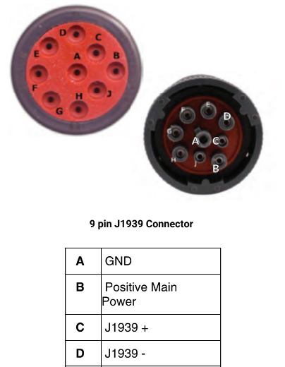
Once you've configured the ECU, you're ready to connect it to the vehicle's J1939/CAN bus connector, this is usually a 9-pin connector, refer to our support site for more information on the location of this connector.
Installation
CAN Bus Wiring Pinout (found in 14-pin molex)
| Syrus Wire Color | Signal | Description | |
|---|---|---|---|
| Yellow | CAN1_H | Primary positive signal of the J1939/FMS bus. Connect to the vehicle's CAN_H cable. This cable is twisted together with the green CAN1_L cable. Green CAN1_L Primary negative signal of the J1939/FMS bus. Connected to the vehicle's CAN_L cable. This cable is twisted together with the yellow CAN1_H cable on the ECU Monitor. Cyan CAN2_H Secondary positive signal of the J1939/FMS bus. Connect to the vehicle's CAN_H cable. This cable is twisted together with the white/light green CAN2_L cable. White Light green CAN2_L | Secondary negative signal of the J1939/FMS bus. Connect to the vehicle's CAN_L cable. This cable is twisted together with the cyan CAN2_H cable.|
Updated 8 months ago
What’s Next
Head to the develop section of the ECU to start with the configuration file on the device.