ADAS
Advanced Driver Assistance Systems
Syrus can interact with Advanced Driver-Assistance Systems accessories which help monitor the road to help avoid collisions & accidents. ADAS accessories notify when a vehicle is close to hitting the vehicle or pedestrian in front of it, including alerts for when the vehicle is swerving on the road without directional signals.
General Overview
- Use the apx-ecu tool to configure the ECU with the compatible ADAS accessory
- Add the ADAS accessory's parameters to the ecu monitor configuration file
- Connect the ADAS accessory to the Syrus
- Install the ADAS accessory in a vehicle
- Receive alerts and information from the ADAS accessory
Installation / Wiring Diagrams

Movon MDAS-9 Syrus 4 Connection Diagram
Read note below on installing aterminating resistor for CAN Bus accessories
Movon MDAS9 &Syrus ECU Pinout
| ADAS Wires | Signal | Description | Syrus Signal | Syrus Wires | |
|---|---|---|---|---|---|
| PIN 1 | CAN_HIGH | CAN High wire from ADAS accessory, connect to the Syrus Cyan CAN2_H data cable. | CAN2_H | Cyan | |
| PIN 2 | CAN_LOW | CAN Low wire from ADAS accessory, connect to the Syrus White/Light Green CAN2_L data cable. | CAN2_L | White | Light Green |
| Red | PWR | Power for the ADAS accessory, use the same power source as the Syrus +12-24V DC. | |||
| Black | GND | ADAS's ground, connect to the Syrus 4 electrical ground cable. | GND | Brown | |
Note be sure to maintain the cables for the ECU monitor twisted.
Movon MDAS-9 Serial
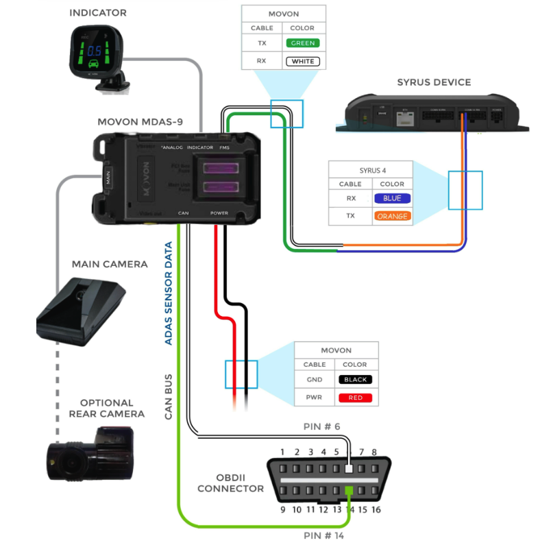
Movon MDAS-9 Serial Syrus 4 Connection Diagram
| ADAS Wires | Signal | Description | Syrus Signal | Syrus Wires | |
|---|---|---|---|---|---|
| Green | TX | TX wire from ADAS accessory, connect to the Syrus RX data cable. | RX | Blue | White | RX | RX wire from ADAS accessory, connect to the Syrus TX data cable. | TX | Orange |
| Red | PWR | Power for the ADAS accessory, use the same power source as the Syrus +12-24V DC. | |||
| Black | GND | ADAS's ground, connect to the Syrus 4 electrical ground cable. | GND | Brown | |
Movon MDAS-9 & Movon MDSM-7 with Syrus 4G
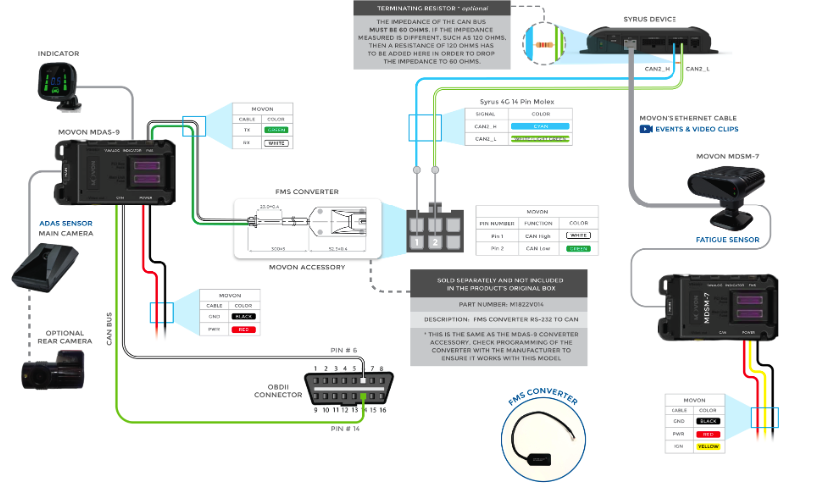
Movon MDAS-9 & MDSM-7 Syrus 4 Connection Diagram

Mobileye 6-8 Syrus 4 Connection Diagram
Note: The Mobileye EyeCAN or CAN Sensor can be used for integrating with the Syrus device
Mobileye 6, 8 &Syrus ECU Pinout
| ADAS Wires | Signal | Description | Syrus Signal | Syrus Wires | |
|---|---|---|---|---|---|
| CAN_HIGH | CAN High wire from ADAS accessory, connect to the Syrus Cyan CAN2_H data cable. | CAN2_H | Cyan | ||
| CAN_LOW | CAN Low wire from ADAS accessory, connect to the Syrus White/Light Green CAN2_L data cable. | CAN2_L | White | Light Green | |
| Blue | IGNITION | Ignition for the ADAS accessory, connect to the Syrus yellow cable. | IGN | Yellow | |
| Red | PWR | Power for the ADAS accessory, use the same power source as the Syrus +12-24V DC. | |||
| Black | GND | ADAS's ground, connect to the Syrus 4 electrical ground cable. | GND | Brown | |
Note be sure to maintain the cables for the ECU monitor twisted.
Installing a Terminating Resistor
Note that the impedance of the CAN bus must be 60 Ohms. To measure the impedance turn off the vehicle and make sure the multimeter is set to measure resistance (20Ω scale), and finally place the red and black probes on the CAN bus, it should be around 60Ω.
When connecting a single Movon device to the CAN bus the impedance of the bus changes to 120Ω, in order to drop it to the required 60Ω value a 120Ω resistor must be placed in parallel at the terminating end of the CAN bus wires of the Syrus 4G CAN High/CAN Low wires.
Any value lower than 60 Ohm indicates that there are probably more than two 120 Ohm bus termination resistors present. A value bigger than 60 Ohm typically indicates that there is at least one bus termination resistor missing or the bus terminators have a wrong resistance value.
Note: If you connect multiple accessories with terminating resistors, for example 2 Movon sensors, the impedance will measure out to be 60 Ohms, meaning you DO NOT have to add a resistor in this case.
The recommended resistances wattage depends on the type of vehicle, for 12V use at least a wattage of 0.5W, and for 24V use a wattage of at least 1W.
Here are some sample resistances you can purchase online; EDGELEC EFR-W1D00-A:MF & KOA Speer MOS1CT528R121J

60 Ohm impedance
Accessory Comparison
| Description | Movon MDAS-9 | Mobileye |
|---|---|---|
| Brakes detecting | ✅ | ✅ |
| FailSafe (Error state) detection | ✅ | ✅ |
| Forward collision warning detection (FCW) | ✅ | ✅ |
| Headway measurement (in meters) | ✅ | 🚫 |
| Headway measurement (in seconds) | ✅ | ✅ |
| Headway valid (boolean) | ✅ | ✅ |
| Left and right signals | ✅ | ✅ |
| Left lane departure warning (LLDW) | ✅ | ✅ |
| Low and high beams detection | 🚫 | ✅ |
| Parked (zero speed) detection | ✅ | ✅ |
| Pedestrian forward collision warning (PCW) | ✅ | ✅ |
| Pedestrian in danger zone | ✅ | ✅ |
| Relative speed from front of vehicle | ✅ | 🚫 |
| Right lane departure warning (RLDW) | ✅ | ✅ |
| Speed limit recognition | ✅ | ✅ |
| Tamper detection (fired when camera is covered) | ✅ | 🚫 |
| Time indicator | 🚫 | ✅ |
| Wipers detection | ✅ | ✅ |
Guide: Movon MDAS-9
To install the Movon MDAS-9 we'll use the ECU Monitor wires, we recommend using the secondary interface for the connection of accessories.
Manufacturer's installation guide
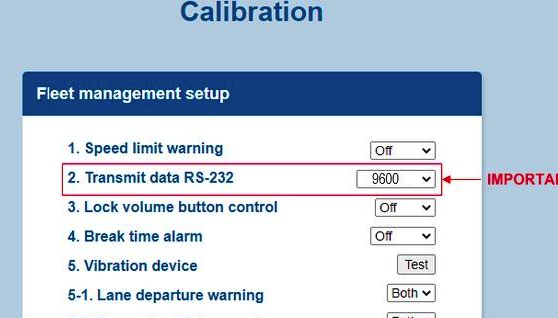
Calibration
Starting at Step 4 in the installation guide, we'll connect MDAS-9 to PC using Micro USB cable in order to pull up the calibration menu.
Below are the calibration options that DCT recommends.

Movon MDAS-9 Version 0.5.12

Camera Detection and Calibration

Events Calibration and Timestamp

Fleet Management Setup and Miscellaneous
Configuration
Once the installation is completed and the ADAS accessory is calibrated you need to add the ADAS parameters to the ECU monitor profile.

Syrus Cloud ECU Profile for Mobileye & Movon Accessories
Guide: Movon MDAS-9 Serial
MDAS- 9 serial is supported from version Apex 24.06.1 beta.
Once the Movon MDAS-9 is connected and calibrated, send the command apx-serial set –mode=mdas9 to SyrusCloud, and check the status with apx-serial-mdas9 status. If the status is connected, put the snippet at the end of the document in the Syrus 4 application and perform tests, if it does not answer connected, see the electrical connection diagram and the necessary configuration of the MDAS9 and Syrus 4.
# Set the serial mode for the Syrus to work with the movon MDAS-9
$ apx-serial set –mode=mdas9

# Get the status
$ apx-serial-mdas9 status
{
  "state": "connected",
  "model": "mdas 9",
  "speed": 0,
  "rpm": 0,
  "left_distance": 0,
  "rigth_distance":0
}
Ensure 9600 in the baud rate section
Once you set the consumption threshold above you can configure a signal to generate an event using Syruslang.
define group movon9

define signal mbly_hdwmsr min_duration=2s $adas.time_to_collision < 2

define signal mbly_hdwmsr_0 min_duration=2s $adas.time_to_collision > 0

define signal sg_adas_connected $adas.connected == true

define signal sg_adas_disconnected $adas.connected == false

define event ev_mdas9_on group=movon9 fieldset=default ack=seq label=mda9son trigger=sg_adas_connected

define event ev_mdas9_off group=movon9 fieldset=default ack=seq label=mdas9off trigger=sg_adas_disconnected

define event ev_brake group=movon9 fieldset=default ack=seq label=mblybrkon [email protected]

define event mobileye_hdwmsr group=movon9 fieldset=default ack=seq label=mblyhdalr trigger=mbly_hdwmsr,mbly_hdwmsr_0,and

define event ev_left_lane group=movon9 fieldset=default ack=seq label=mblylldw code=11 [email protected]_lane_departure_warning

define event ev_right_lane group=movon9 fieldset=default ack=seq label=mblyrldw code=12 [email protected]_lane_departure_warning

define event ev_ecmblkd_lowv group=movon9 fieldset=default ack=seq label=camblock code=18 [email protected]

define event ev_pedestrian_warning group=movon9 fieldset=default ack=seq label=mblypdpcw code=17 [email protected]_collision_warning

define event ev_forward_collision group=movon9 fieldset=default ack=seq label=mblypdfcw code=19 [email protected]_collision_warning

define event ev_front_prosimity_w group=movon9 fieldset=default ack=seq label=mblypdfpw code=20 [email protected]_proximity_warning

define event ev_ecmblkd_lowv group=movon9 fieldset=default ack=seq label=camblock code=18 [email protected]_blocked

define event ev_ecm_lowv group=movon9 fieldset=default ack=seq label=camlowvis code=21 [email protected]_visibility

# destinations

set destinations group=movon9 pegasus
More information Configurate Movon MDAS-9 via serial port
Guide: Mobileye 6, 8
To install the Mobileye 6, 8 series we'll use the ECU Monitor wires, we recommend using the secondary interface for the connection of accessories.
Manufacturer's installation guide
Configuration
Once the installation is completed and the ADAS accessory is calibrated you need to add the ADAS parameters to the ECU monitor profile.

Updated 8 months ago