Fatigue sensor
Documentation page for the Syrus IoT Telematics Gateway
Syrus can communicate with fatigue sensor accessories which help monitor driver's fatigue. Fatigue sensors work by analyzing a driver's facial features and their environment to generate audible alerts as well as capture a photo or video when the driver starts to doze off or feel drowsy. Together with Syrus you can get notified whenever one of these fatigue alerts are triggered and view the captured photo/video clip associated with each fatigue event.
General Overview
- The way it works is that you connect one of the compatible fatigue sensors to the Syrus
- Depending on which fatigue sensor you connected you will either configure Syrus to use the serial (rs232), can bus, or ethernet interfaces to obtain the fatigue sensor's data
- Once connected and configured using the appropriate tool look at the fatigue sensor and simulate drowsiness
- For the serial rs232 interface use the serial tab or the apx-serial tool to view data
- For the ecu interface look at the ECU tab or the apx-ecu tool to
list_parametersthat start with the CAN_ID of the accessory (ex: 600_4.1_1) - For the ethernet interface look at the video tab or the apx-video tool to get the video status
Installation / Wiring Diagrams

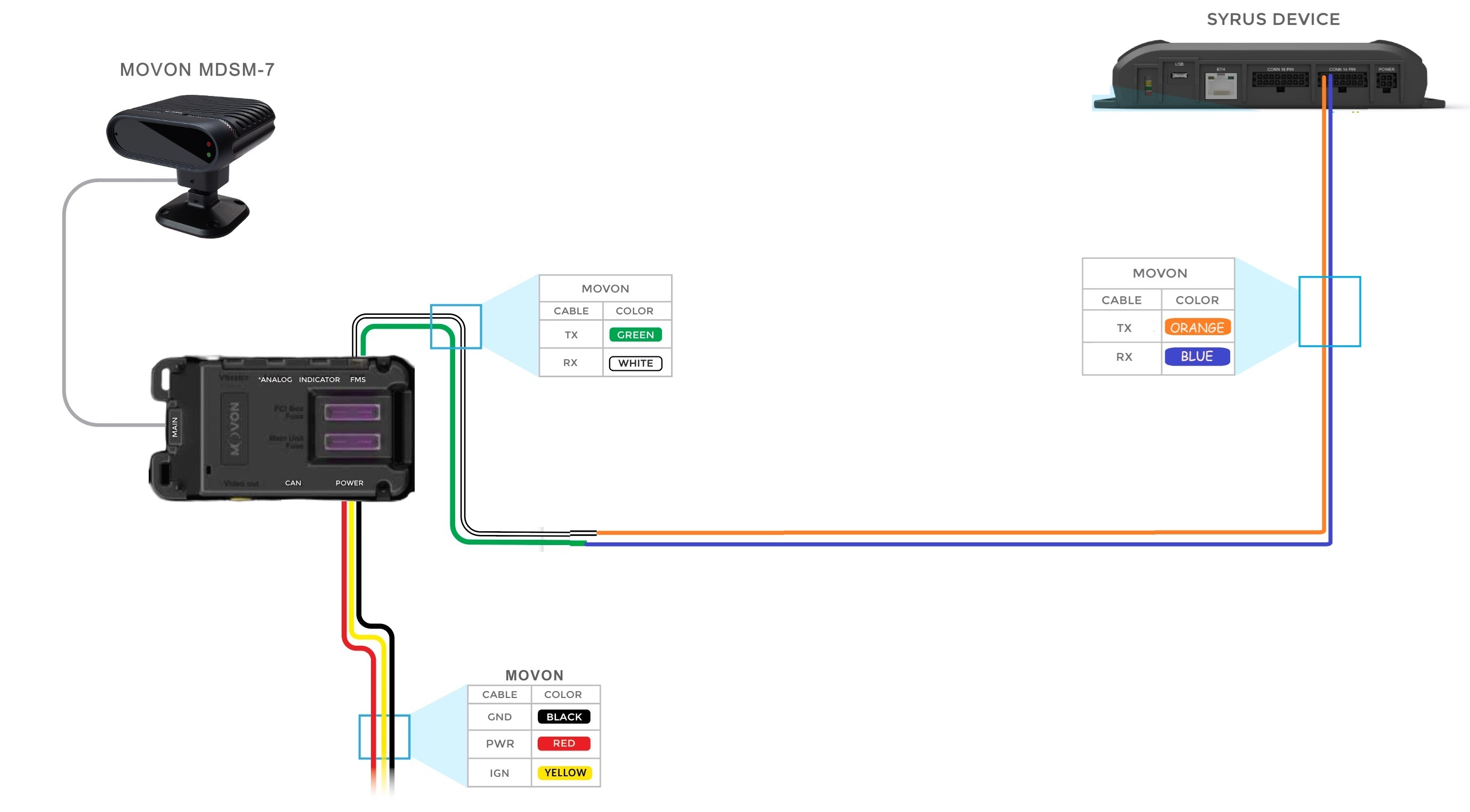
Movon MDSM-7 Option A - via Ethernet (Includes video clips)

Movon MDSM-7 Option A
The video clips recording requires a firmware version for Movon's hardware of at least 0.3.04 or newer
Movon MDSM-7 Option B - via CAN bus

Movon MDSM-7 Option B
Read note below on installing aterminating resistor for CAN Bus accessories
Movon MDSM-7 Option C - via serial connection
Movon MDSM-7 Option C
Movon MDSM-7 & MDAS-9 Syrus 4 integration
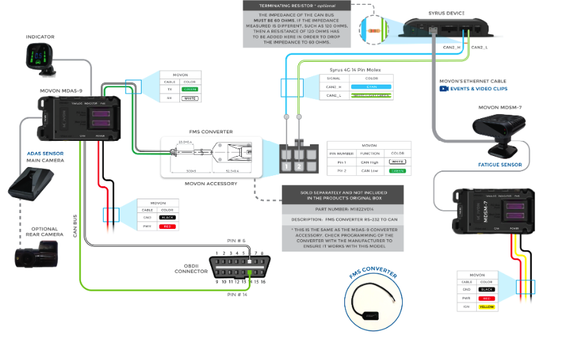
Movon MDSM-7 & MDAS-9 Syrus 4 Connection Diagram

Caredrive Fatigue Sensor
Installing a Terminating Resistor
Note that the impedance of the CAN bus must be 60 Ohms. To measure the impedance turn off the vehicle and make sure the multimeter is set to measure resistance (20Ω scale), and finally place the red and black probes on the CAN bus, it should be around 60Ω.
When connecting a single Movon device to the CAN bus the impedance of the bus changes to 120Ω, in order to drop it to the required 60Ω value a 120Ω resistor must be placed in parallel at the terminating end of the CAN bus wires of the Syrus 4G CAN High/CAN Low wires.
Any value lower than 60 Ohm indicates that there are probably more than two 120 Ohm bus termination resistors present. A value bigger than 60 Ohm typically indicates that there is at least one bus termination resistor missing or the bus terminators have a wrong resistance value.
Note: If you connect multiple accessories with terminating resistors, for example 2 Movon sensors, the impedance will measure out to be 60 Ohms, meaning you DO NOT have to add a resistor in this case.
The recommended resistances wattage depends on the type of vehicle, for 12V use at least a wattage of 0.5W, and for 24V use a wattage of at least 1W
Here are some sample resistances you can purchase online; EDGELEC EFR-W1D00-A:MF & KOA Speer MOS1CT528R121J

Accessory Comparison
| Description | Movon MDSM-7 | Caredrive MR688B | Cipia-FS10 |
|---|---|---|---|
| Captures photos of incidents | ✅* | ✅ | ✅ |
| Captures videos of incidents | ✅* | 🚫 | ✅ |
| Configure parameters like sensitivity and speaker volume remotely | 🚫 | ✅ | ✅ |
| Driver fatigue warning/yawning | ✅ | ✅ | ✅ |
| Driver fatigue alarm/drowsiness | ✅ | ✅ | ✅ |
| Driver distracted | ✅ | ✅ | ✅ |
| Driver absent/not detected | ✅ | ✅ | ✅ |
| Driver disappeared | 🚫 | 🚫 | ✅ |
| Driver changed | 🚫 | 🚫 | ✅ |
| Driver identified | 🚫 | 🚫 | ✅ |
| Unknown driver | 🚫 | 🚫 | ✅ |
| Driver on phone | ✅ | 🚫 | ✅ |
| Driver smoking | ✅ | 🚫 | ✅ |
| Tamper alert | ✅ | 🚫 | ✅ |
| Fatigue sensor power ON | 🚫 | 🚫 | ✅ |
| Fatigue sensor power OFF | 🚫 | 🚫 | ✅ |
| Driving with no seatbelt | 🚫 | 🚫 | ✅ |
| Camera blocked | ✅ | 🚫 | ✅ |
| Zero speed detected | ✅ | 🚫 | 🚫 |
| System diagnostic messages (bootup ok, bootup failure) | 🚫 | 🚫 | ✅ |
| System diagnostic message camera loss of gps | 🚫 | 🚫 | ✅ |
| System diagnostic message camera uncalibrated | 🚫 | 🚫 | ✅ |
- Note that the Movon MDSM-7 is configured for either Photos or Videos, but not both.
✅ - Available and supported
🔲 - Available and not yet supported
🚫 - Not available
Guide: Cipia-FS10 via Syrus 4G
The Cipia-FS10 will communicate via Wifi with Syrus 4. In order to get started make sure you download the latest apex OS version.
What you'll need:
- 1 Syrus 4 device (Required Apex 23.32.4 or newer)
- 1 Cipia-FS10 device with installation kit
- Calibration board
- 1 Android phone for installing (Android v8 or newer)
- 1 Micro SD card
Credentials you'll need
- Cipia EyeSightInstaller mobile application
-
- Email, Password, Server URL
- Cipia-FS10 unit
-
- Device password
Cipia Setup
Step 1
Connect an SD card to the Syrus and be sure it's formatted and detected, you can do this from the Management Tool -> System -> Storage section.

Step 2
Configure the Cipia's MAC address and UnitID (found on the Cipia's sticker) to the Syrus using the apx-ndm-cipia tool.
WarningMAC address and UnitID are needed to load the CipiaFS10 configuration file via Syrus4 apx-ndm-cipia tool.
# Apex 22.47.1 or newer
$ sudo apx-ndm-cipia set --mac=A6:04:50:3C:DA:45 --id=e320290294

# Apex 22.28.1 - 22.47.0
$ sudo apx-video set --device=cipia_fs10 --mac=A5:53:0C:CB:DC:1D --id=e123456789

# Apex 22.27.1 or older
$ sudo apx-video set_mac --device=cipia_fs10 --mac=A5:53:0C:CB:DC:1D
Step 3
Create a video profile for Cipia in Syrus Cloud

To do this simply create a new video profile, add a camera, and select Cipia from the dropdown menu.
WarningNote that once the Video profile is synchronized with the Syrus it automatically bring up the Syrus 4 hotspot. Thus you will lose wifi connectivity.
Step 4
Configure the hotspot settings on the Syrus using the apx-hotspot.
# set the SSID and  Password
$ sudo apx-hotspot set --ssid=syrushotspot --pass=syrus1234
Step 5
Download the configuration and settings file and edit the settings according to the hotspot values entered previously.
Configuration File: cipia_fs10.conf.json
Settings File: cipia_fs10.settings.json
{
    "WifiSettings": {
        "APModeEnable": true,
        "APPassword": "1234567890",
        "APSSID": "FS-WiFi",
        "Password": "syrus1234",    # hotspot password
        "SSID": "syrushotspot"      # hotspot ssid
    }
}
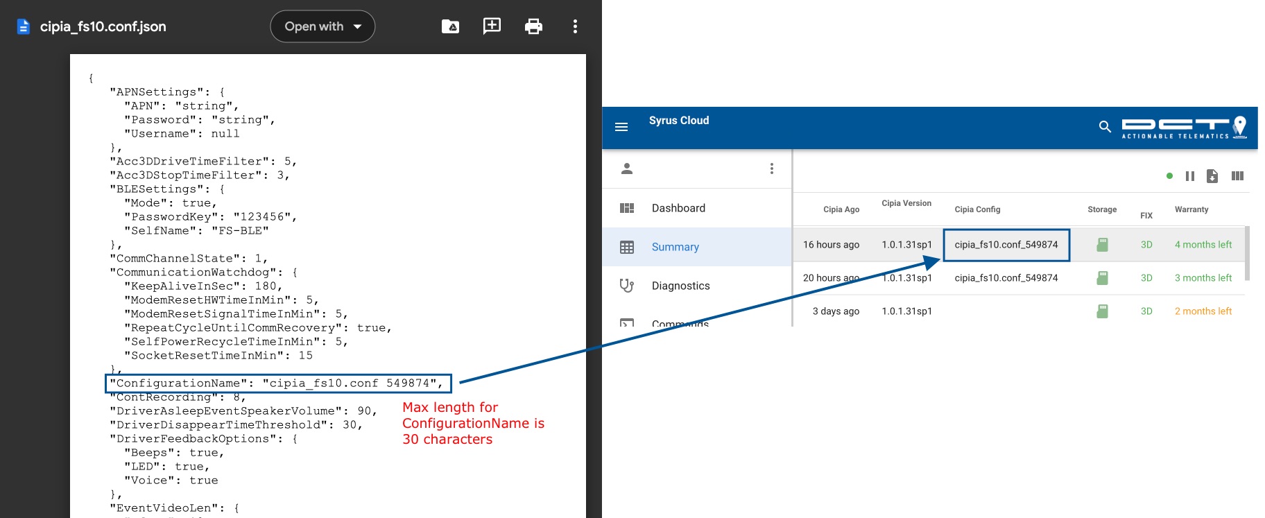
Adding a custom configuration name for CipiaYou can use the
ConfigurationNamein the cipia_fs10.conf.json to give the configuration a custom name. The results will show up in Syrus Cloud under the Cipia Config column.Note that the max length for this name is 30 characters long.
Once you're done editing the configuration & settings file you can use Syrus Cloud upload functionality to load it on the Syrus.
| file | path to upload to |
|---|---|
| cipia_fs10.conf.json | /data/users/syrus4g/video/cipia_fs10.conf.json |
| cipia_fs10.settings.json | /data/users/syrus4g/video/cipia_fs10.settings.json |

Step 6
Calibrate and install the camera in the car.
Download and install the Cipia EyeSightInstaller Mobile application Android APK.
Note that this application requires Android 8 or above
Login with the provided Installer Email, Password, and Server URL.

Step 7
Follow the screen prompts and unscrew the side compartment and insert the micro SD card.

Step 8
Use your phone's Wifi to connect to the Cipia's access point. Look for FS-WiFi-XXXXXX

Click on the I'm connected button to confirm that you're connected to the Cipia unit.

Once connected enter the device password, this will be supplied along with the installation app's credentials, and click on Install a new device

Step 9
Follow the instructions and enter your vehicle's information along with the Ver0.26-WiFi configuration file.

Step 10
If you are using an apex version above 22.47.1 with apx-ndm-cipia, you can configure the unit with the configure command, this command uses the MAC Address and the ID previously stored to find the WiFi network provided by the CipiaFS10.
# Configure Cipia on the Syrus

$ sudo apx-ndm-cipia configure

$ sudo apx-ndm-cipia configure
"Please electrically reboot your cipia device"

# Once you get the successful configuration message restart the Cipia electrically
WarningIn case the configuration fails by showing the "Network not found" message, remember that by default the WiFi network SSID provided by the CipiaFS10 will have the following structure:
FS-WiFi-XXXXXXXX where the XXXXXXX are the last 8 characters of the CipiaFS10 MAC
So you have to validate that the saved MAC is OK, and additionally you can search for the network you expect to find using the command apx-wifi scan
After restarting the Cipia you can verify that it's working with the status command
$ sudo apx-ndm-cipia status
{
    "id": "E321290499",
    "mac": "A4:04:50:3C:BE:57",
    "version": "1.0.1.30rc2",
    "ip": "192.168.2.10",
    "connection": {
        "state": "CONNECTED",
        "since": 1671119309
    }
}
If you have an older version of Apex select the Communication channel Wifi, and using the settings from the first 2 steps enter the Wi-Fi settings.
Wi-Fi settings
| field | description | default | sample |
|---|---|---|---|
| Wifi SSID | Syrus 4 hotspot SSID | Syrus4G-LTE | syrushotspot |
| Wifi password | Syrus 4 hotspot password | syrus1234 | syrus1234 |
| Server address/IP | Syrus 4 hotspot ip address (inet addr) | 192.168.2.1 | |
| Port | Default port for Syrus 4 Cipia integration | 1883 |
Change any of the device settings if desired.

Step 11
Device Test, Calibration, and Driver Enrollment
The calibration of the Cipia is done by attaching the provided Checkerboard square to the headrest of the car seat, and moving the seat back and forth slowly. You can download a sample checkerboard square from the following link.

Keep following the onscreen prompts to test the device, and register a driver.
Note that the driver registration is required if you want to trigger the events for driver detection.

Step 12
At this point the installation is complete and you can use the Syruslang fatigue sensor section to start detecting events.
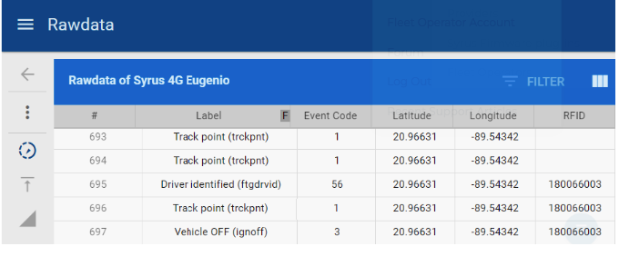
Cipia driver identification in Pegasus
Cipia can recognize a driver based on its face and associate it with an ID. Now we can use this with Syrus 4 to associate an ID from Cipia to an asset from Pegasus. This feature works on APX 24.09.4 or above and SyrusJs 1.62.6 or above.
Once you finish the Cipia and Syrus 4 configuration, follow these steps:
- In Syrus Cloud create an instance.
- Add the RFID tag on the fieldset using this component: $fatigue_sensor.driver_name.
We recommend the RFID tag because it supports alphanumeric characters, for example:
define fieldset default fields=$io,$gnss,$modem,$battery,RI:$fatigue_sensor.driver_name- Create an event that fires with driver recognition. This event helps notify every time a new driver is detected and update the ID on Pegasus immediately.
define event ev_fatigue_driver_ident ack=seq fieldset=default group=fatigue_cipia label=ftgdrvid code=56 trigger=@fatigue_sensor.driver_identified- Test it!
Troubleshooting
If you are unsure of the Cipia's MAC address, follow this procedure to find it:
# assuming you have the default network credentials, connect to Cipia
$ sudo apx-wifi add FS-WiFi-503cbe57 1234567890

# verify the connection
$ sudo apx-wifi status
{"mac":"FC:45:C3:8F:C6:D8","state":"completed","ssid":"FS-WiFi-503cbe57","signal":"-46","key_mgmt":"WPA-PSK","ip":"","rx_bytes":"1751","tx_bytes":"4111"}

# get the Cipia IP (inet addr)
$ ifconfig
wlan0     Link encap:Ethernet  HWaddr FC:45:C3:8F:C6:D8
          inet addr:192.168.42.14  Bcast:192.168.42.255  Mask:255.255.255.0
          ...

# ping the Cipia gateway (.1 address)
$ ping 192.168.42.1

# query the ARP table
$ cat /proc/net/arp
192.168.42.1     0x1         0x2         a6:04:50:3c:be:57     *        wlan0

# note that this is the MAC of the local access point, change the first two letters from a6 to a4 and that's the MAC of the Cipia's wifi
If you have a device stop sending videos via the Cipia FS-10 you can perform a restart by sending the following commands using Syrus Cloud:
# restart the video module
apx-video restart --module=ndm

# wait for 1 minute and query the Syrus hotspot status
apx-hotspot status

# once the hotspot is active you can restart the Cipia device by pressing the power button
# verify that the Cipia is connected with
apx-video status
Other helpful commands
# verify if a Cipia camera is connected to the Syrus' hotspot
apx-hotspot list

# restart the Syrus
apx-system reboot

# verify the status of the ignition
# most installations use the ignition switch to power on the Cipia so it must be ON to detect the Cipia camera
apx-io get ign

# consult the Cipia device MAC
# this MAC address should match the same one found in the apx-hotspot list
apx-video get --device=cipia_fs10 --mac
Guide: Cipia FS10 via Syrus 4G Lite
step 1
Install Apex 24.23.1 or above (a full Apex Update is required to have the device work with the new USB dongle) and make sure the Cipia FS10 WiFi (local) has version 1.0.2.32 or newer (follow this procedure for updating it locally or remotely)
step 2
Connect the TP-Link AC600 Archer T2U Nano to the USB port (note that when using the microUSB connector from Syrus it disables the USB port, so you can’t load up the management tool interface while connecting with the dongle, it’s recommended to do everything remotely via Syrus Cloud). Use apx-wifi scan to check that the wifi dongle is working properly.
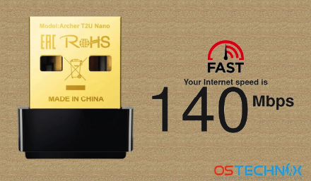
TP-Link AC600 Archer T2U Nano
step 3
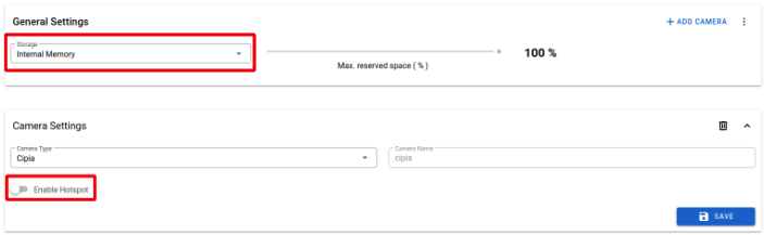
Use Syrus Cloud to install a Cipia camera profile to the device. Be sure to select internal memory for storage and disable the hotspot mode.
step 4
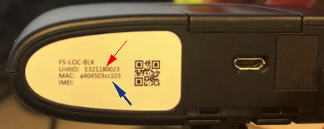
Use the apx-ndm-cipia tool to set the Cipia MAC address and ID to the Syrus device: apx-ndm-cipia set --mac=a404503cbff2 --id=E321290071
You can find the MAC address and ID in the back part of the Cipia camera.
step 5
Download the Cipia configuration files from the following link and edit the settings
https://syrus.digitalcomtech.com/docs/driver-monitoring-dashcam-solution#connect-the-dms
Configuration File: cipia_fs10.conf.json
Settings File: cipia_fs10.settings.json
Edit the cipia_fs10.settings.json file with the following parameters
{
	"WifiSettings": {
    	"APModeEnable": true,
    	"APPassword": "1234567890",
    	"APSSID": "FS-WiFi",
    	"Password": "",
    	"SSID": ""
	}
}
Edit the final part of the cipia_fs10.conf.json file with the following parameters:
   "ServerAddress": "192.168.42.100",
   "ServerPassword": "fs1Manager@2021",
   "SleepModeTO": 5,
   "SpeakerControl": false,
   "SpeakerVolume": 90,
   "SystemLEDActivation": true,
   "TelematicsDataForwardOptions": 0,
   "VideosStorageNumber": 250,
   "VoiceNotificationsLang": 1
 }
Upload the edited files to the Syrus device in /data/users/syrus4g/video/ folder.
step 6
Configure the Syrus device to use 192.168.42.100 as its IP address for Wifi mode.
apx-wifi set --ip=192.168.42.100/24Start the wifi service
apx-wifi startConfigure Cipia with the following command
apx-ndm-cipia configureOnce configured, the following message should be displayed:
please electrically reboot your cipia device
Retry in case of failure
Restart the Cipia device by disconnecting the power supply, wait until the camera’s LED is completely off, and then connect the camera again.
Use apx-ndm-cipia status to check if the camera was detected and the Cipia version is 1.0.2.32 or above.
{
  "id": "E321290071",
  "mac": "a404503cbff2",
  "version": "1.0.2.32_b8test",
  "configuration": "cipia_fs10.conf 549874",
  "ip": "192.168.42.1",
  "connection": {
	"state": "CONNECTED",
	"since": 1716918909
  },
  "name": "cipiaFS10",
  "type": "cipiaFS10"
}
step 7
Depending on your requirements, install a syrusjs application and configure Cipia events. Remember that the Cipia videos can also be downloaded by using the Syrus Cloud web site
Cipia Firmware Update Procedure
Procedure for updating the Cipia firmware locally and remotely. It has been tested with Cipia FS-10 (Locally connected) and Cipia FS-10 Plus (LTE) devices.
Local / Update from Windows Computer
Requirements:
- Windows PC
- Cipia Device
- MicroUSB *optional (if you choose this option you may need to download an additional driver)
- CipiaTool - download (This tool can be used both for diagnostics and FW updates)
- Latest firmware - download (At the time of this document the latest stable versión was 1.0.2.32). Other versions
Step 1
Connect PC to Cipia-FS10 local WIFI (FS-WiFi-…).Default Password is 1234567890
Step 2
Run the Software and you will see a screen that looks like this:
The default Cipia IP is 192.168.42.1
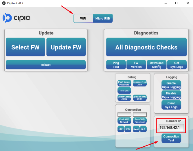
You can click on Connection Test to verify that the Cipia is detected.
Remotely Using Syrus 4
To update the Cipia remotely using Syrus 4 devices, you need to first contact Cipia ([email protected]) and pass them the Cipia IDs that you want to update, and to which version. Example:
Cipia IDs
E321460607
E321460654
E321460447
Version = 1.0.2.32
step1
Once Cipia confirms everything is ready on their side, do the following:
- Send the Update command
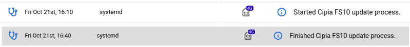
apx-ndm-cipia update. This command will allow the Syrus to ping Cipia’s servers for up to 30 mins to attempt to update it remotely.
- Electrically reset the Cipia (or wait til next Power cycle, the Cipia goes into sleep mode if it’s parked)
- Check the Cipia version
apx-ndm-cipia get --firmware_version

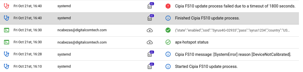
If the process failed then try again, and verify with Cipia that the version on their end is the correct one.
For versions with older Apex 22.51.1
- Send
apx-video update --device=cipia_fs10
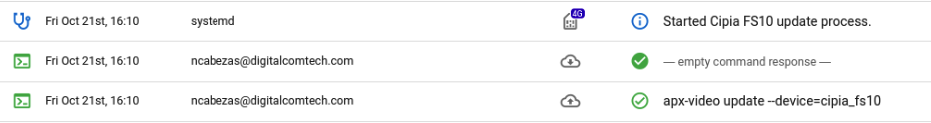
- Syrus4 device is going to give internet access to cipia for 30 minutes, For now syrus does not have the way to check if cipia was correctly updated, so you are going to see something like this, which is normal.
- To check if the OTA process finished correctly, execute an electrical reset on the Cipia device and once it goes available again send apx-video get --device=cipia_fs10 --version to check the new version of the Cipia.
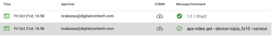
- If the version is not the version you are waiting for, start the process again.
Guide: Movon via Ethernet
The first option for installing the Movon MDSM-7 will use the Ethernet cable, this option is generally cleaner and less hassle as there's a more direct connection with the Movon and all the events can be generated as well as video clips received.
Movon Setup
We need to access the Movon's Calibration Interface in order to setup the video capturing capability and enable communication with Syrus.
To do so we must connect via USB and enter the IP address and port of the Movon accessory on a browser (<<<http://20.0.0.1:18087/>>>), see the PC Calibration section of the manufacturer's installation guide for more information.
Firmware / OS Version for MovonNote that the MDSM-7 firmware that DCT tests was 0.3.04, however DCT has found that some Movon devices with this version still cause issues detecting the video, you have to reflash the device with the same 0.3.04 version to fix it.
Once connected to the Movon you'll be guided through the calibration process.

Once you complete the calibration you'll be taken back to the main screen where you'll have the option to upgrade the firmware.
Start by downloading and extracting the following compressed file which contains a binary pkg in order to upgrade the Movon to the necessary firmware version (v0.3.04).
Step 1
Select Firmware update

Step 2
Select the extracted file mdsm7_0.3.04.pkg from the compressed zip downloaded earlier.

Wait a few minutes while the firmware is updated.
Step 3
Once the firmware is updated go back to the main menu and go through the Calibration again.
Go through the steps on screen to detect the speed (recommended CAN speed) and perform the Auto Camera Setting.
Once you get to the DVR Setup you can use the following settings:

Step 4
The DSM Setup allows you to enable/disable specific signals.

Step 5
The Auto Camera Setting handles the driver detection and ensure the whole face is captured.

Step 6
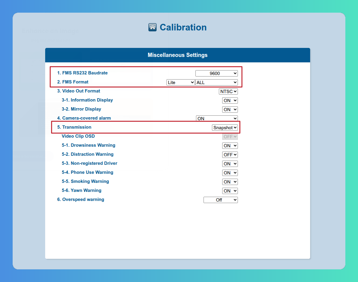
Under the miscellaneous settings select Video clips and underneath which events you want to capture video clips with.
WARNING
- Make sure the FMS RS232 Baudrate is OFF .
- Make sure the FMS Format is in Standard, the connection via Ethernet only supports the Standard mode.
- Make sure the Video Out Format is in PAL mode.
- Make sure the Transmission mode is set to VideoClip. The Ethernet connection only supports video transmission and will only display events when video is enabled.

Camera Blocked EventFor versions of the syrus-ndm application earlier than 0.7.1, the Camera Blocked event was not being considered. If you want to see this event, as well as the camera_fail, gps_fail, and can_fail errors, update the application package to the latest available version using the command:
apx-core install syrus-ndm and apx-core install syrus-efs.This event does not have media.
Once the calibration is complete export your settings so you can copy them to other devices

Step 7
Next from the Movon's main menu go to the Ethernet Settings

this opens up the Network settings, start by making sure DHCP is disabled in the first section.
The IP address of the first section is the IP address of the MDSM-7, be sure to select an IP address within the same subnet as the bottom section's IP address. The bottom section's IP address is the one we're going to configure on the Syrus in the nexts step.
Make sure to activate the TCP/IP FMS Activation and enter the IP address of the Syrus 4 ethernet interface, along with a port ranging from 61500 - 61550.
Once done, click on the right arrow to proceed and save the configuration.

Step 8
Finally go into the Accessories -> Video section of the Syrus 4 Management UI and enter the general settings; where you'll save the location of the video storage and max allowed space.
Click on the top right button to add a new camera and select type MDSDM-7 and enter the same IP address and port from Step 7 above (be sure to enter the IP address of the bottom section of the Network configuration from Step 7)

At this point it's done, you're ready view the messages published via redis or configure a Syruslang script to report fatigue events.
Guide: Movon via CAN Bus
The second option installing the Movon MDSM-7 will use the ECU wires of the CAN bus, we recommend using Syrus' secondary interface for the connection.
CAN Bus Wiring Pinout (found in 14-pin molex)
| MDAS-7 Wires | Signal | Description | Syrus Signal | Syrus Wires | |
|---|---|---|---|---|---|
| White | CAN High | Pin 1 - CAN High cable from Movon, connect to Syrus cyan CAN 2 High cable. | CAN2_H | Cyan | |
| Green | CAN Low | Pin2 - CAN Low cable from Movon, connect to Syrus white/light green CAN 2 Low cable. | CAN2_L | White | Light-Green |
| Red | PWR | Power for the Fatigue sensor accessory, use the same power source as the Syrus +12-24V DC. | |||
| Black | GND | Fatigue sensor's ground, connect to the Syrus 4 electrical ground cable. | GND | Brown | |
Note be sure to maintain the cables for the ECU monitor twisted.
Movon Setup
We need to access the Movon's Calibration Interface in order to setup the video capturing capability and enable communication with Syrus.
To do so we must connect via USB and enter the IP address and port of the Movon accessory on a browser (<<<http://20.0.0.1:18087/>>>), see the PC Calibration section of the manufacturer's installation guide for more information.
Once connected to the Movon you'll be guided through the calibration process.

Step 1
Go through the steps on screen to detect the speed (recommended CAN speed) and perform the Auto Camera Setting.
Once you get to the DSM Setup you can enable/disable specific audible events.

Step 2
The Auto Camera Setting handles the driver detection and ensure the whole face is captured.

Step 3
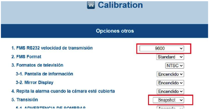
Under the miscellaneous settings select the Snapshot and underneath which events you want to capture photos with.
SnapshotsNote that although Snapshot Transmission is selected no photos are captured with the MDSM7 at this time.

Once the calibration is complete export your settings so you can copy them to other devices

At this point connect the Movon to the vehicle's CAN bus interface following the manufacturer's instruction.
Syrus Configuration
For the configuration of option B (over ECU) we'll create an ECU Profile in Syrus Cloud to configure the Syrus.
Be sure to select the Accessories configuration depending on the CAN interface you use (Primary or Secondary), and select ALL Movon parameters.

Once the Syrus has the profile, and you install the Movon MDSM-7 you can trigger the fatigue sensor messages and trigger messages using Syruslang.
You can also use the apx-ecu tool to view the parameters.
# List ECU parameters, indicating a driver on the phone and yawning
$ sudo apx-ecu list_parameters
{
    "630_1.1_movon": 0,
    "630_1.2_movon": 0,
    "630_1.3_movon": 1
    "630_1.4_movon": 1,
    "630_1.5_movon": 0,
    "630_1.6_movon": 0,
    "630_1.7_movon": 0,
    "630_1.8_movon": 0,
}
The list of parameters and their respective unique CAN_ID are:
| ECU Unique ID | Description |
|---|---|
630_1.1_movon | Drowsiness |
630_1.2_movon | Distraction |
630_1.3_movon | Yawning |
630_1.4_movon | Phone |
630_1.5_movon | Smoking |
630_1.6_movon | Driver absence |
630_1.7_movon | Camera blocked |
630_1.8_movon | Camera error |
Guide: Movon via Direct Serial Port
MDSM 7 per serial port is supported starting with Apex 23.51.2.
To configure send the following command in Syrus Cloud:
$ apx-serial mode mdsm7

#check the status
$ apx-serial-mdsm7 status
{
  "state": "connected",
  "model": "mdsm7",
  "version": 0.3.26-2.1,
  "max_photos": 25,
  "nbr_photos": 2,
  "latest_photo":"1708443088.phone.jpg"
}
If the status is connected, put the snippet at the end of the document in the application of the Syrus 4 equipment and perform tests, if it does not answer connected, see the electrical connection diagram and the necessary configuration of the Movon 7 to work with Syrus 4.
WARNING
- Make sure the FMS RS232 Baudrate is 9600 .
- The FMS Format can be in Standard or Lite, the direct connection via Serial supports the both modes.
- Make sure the Transmission mode is set to Snapshot. The Serial connection only supports snapshot transmission.
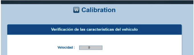
If you want to generate events while it is not moving, to test on the desktop, set the speed to zero “0”.
Camera Blocked EventFor versions of the syrus-ndm application earlier than 0.7.1, the Camera Blocked event was not being considered. If you want to see this event, as well as the camera_fail, gps_fail, and can_fail errors, update the application package to the latest available version using the command:
apx-core install syrus-ndm and apx-core install syrus-efs.This event does not have media.
Guide: Movon via Serial Expander
MDSM 7 per serial expander is supported starting with Apex 23.51.2. The connection via Serial Expander only supports the lite mode.
To configure send the following commands in Syrus Cloud:
$ apx-serial mode serial_expander
$ apx-serial-ext set --portX=mdsm7 (Replace portX with the port of your choice between port1, port2 or port3)

#Check the status
$ apx-serial-exp state
{
  "port1_mode": "mdsm7",
  "state": "connected",
  "port2_mode": "modem",
  "port3_mode": "mdt"
}
If the status is connected, put the snippet at the end of the document in the application of the Syrus 4 equipment and perform tests, if it does not answer connected, see the electrical connection and the necessary configuration of the Movon 7 to work with Syrus 4.
WARNING
- Make sure the FMS RS232 Baudrate is 9600 .
- The FMS Format must be in Lite, the connection via Serial Expander only supports the lite mode.
- Make sure the Transmission mode is set to Snapshot. The Serial connection only supports snapshot transmission.
If you want to generate events while it is not moving, to test on the desktop, set the speed to zero “0”.
Camera Blocked EventFor versions of the syrus-ndm application earlier than 0.7.1, the Camera Blocked event was not being considered. If you want to see this event, as well as the camera_fail, gps_fail, and can_fail errors, update the application package to the latest available version using the command:
apx-core install syrus-ndm and apx-core install syrus-efs.This event does not have media.
Syruslang configuration
define group fatigue
define event fatigue_warning fieldset=defeault ack=seq group=fatigue photo=fatigue_sensor.fatigue_warning label=ftgwarning code=110 trigger=@fatigue_sensor.fatigue_warning
define event fatigue_alarm fieldset=defeault ack=seq group=fatigue photo=fatigue_sensor.fatigue_alarm label=ftgalarm code=111 trigger=@fatigue_sensor.fatigue_alarm
define event fatigue_distraction fieldset=defeault ack=seq group=fatigue photo=fatigue_sensor.distraction label=ftgdistrct code=112 trigger=@fatigue_sensor.distraction
define event fatigue_phone fieldset=defeault ack=seq group=fatigue photo=fatigue_sensor.phone label=ftgcamphon code=113 trigger=@fatigue_sensor.phone
define event fatigue_smoking fieldset=defeault ack=seq group=fatigue photo=fatigue_sensor.smoking label=ftgcamsmok code=114 trigger=@fatigue_sensor.smoking
define event fatigue_cam_blocked fieldset=defeault ack=seq group=fatigue label=ftgcamblck code=115 trigger=@fatigue_sensor.camera_blocked
define event fatigue_camera_fail fieldset=defeault ack=seq group=fatigue label=ftgcamfail code=116 trigger=@fatigue_sensor.camera_fail
define event fatigue_gps_fail fieldset=defeault ack=seq group=fatigue label=ftggpsfail code=117 trigger=@fatigue_sensor.gps_fail
define event fatigue_can_fail fieldset=defeault ack=seq group=fatigue label=ftgcanfail code=118 trigger=@fatigue_sensor.can_fail
set destinations group=fatigue pegasus
More information Movon MDSM-7 configuration via Serial Port
Guide: Caredrive MR688B
Manufacturer's installation guide
To install the Caredrive MR688B, we'll use the Syrus serial RX/TX wires.
Serial Wiring Pinout (found in 14-pin molex)
| Caredrive Wires | Signal | Description | Syrus Signal | Syrus Wires |
|---|---|---|---|---|
| Blue | RX | Caredrive RX (MR688B 232 data receiver), connect to the Syrus orange data transmitter cable. | RS232_TX | Orange |
| Green | TX | Caredrive TX (MR688B 232 data transmission), connect to the Syrus blue data receiver cable. | RS232_RX | Blue |
| Red | PWR | Power for the Caredrive accessory, use the same power source as the Syrus +12-24V DC. | ||
| Black | GND | Caredrive's ground, connect to the Syrus 4 electrical ground cable. | GND | Brown |
Syrus Configuration
Once you have the Caredrive fatigue sensor accessory connected to the Syrus you can configure the serial port to fatigue_sensor mode with the apx-serial tool.
$ sudo apx-serial mode fatigue_sensorTo test the communication with the accessory, you can use the capture command.
$ sudo apx-serial fatigue_sensor capturea photo is captured and automatically uploaded to the default directory: /data/users/syrus4g/fatigue_sensor.
Before your first drive it's important to change the default settings, here's some recommended apx commands you can use to program the camera for 'normal' operation.
# Set sensitivity to 2.9 seconds
$ sudo apx-serial fatigue_sensor sensitivity 3

# Set minimum speed to 30kph
$ sudo apx-serial fatigue_sensor min_speed 30

# Set speeding alarm threshold to 135kph
$ sudo apx-serial fatigue_sensor speeding 135

# Set the speaker volume to low
$ sudo apx-serial fatigue_sensor speaker_volume 1
Ensure the changes are saved by turning the fatigue sensor off and back on.
Note that some fatigue sensors include dip switches on the back of the camera that override these settings. Follow the recommended settings in the manual of the fatigue sensor

Updated 9 months ago