Inputs/Outputs
Syrus 4G includes 7 inputs, 4 outputs, and 4 analog inputs on it's 16-pin molex.
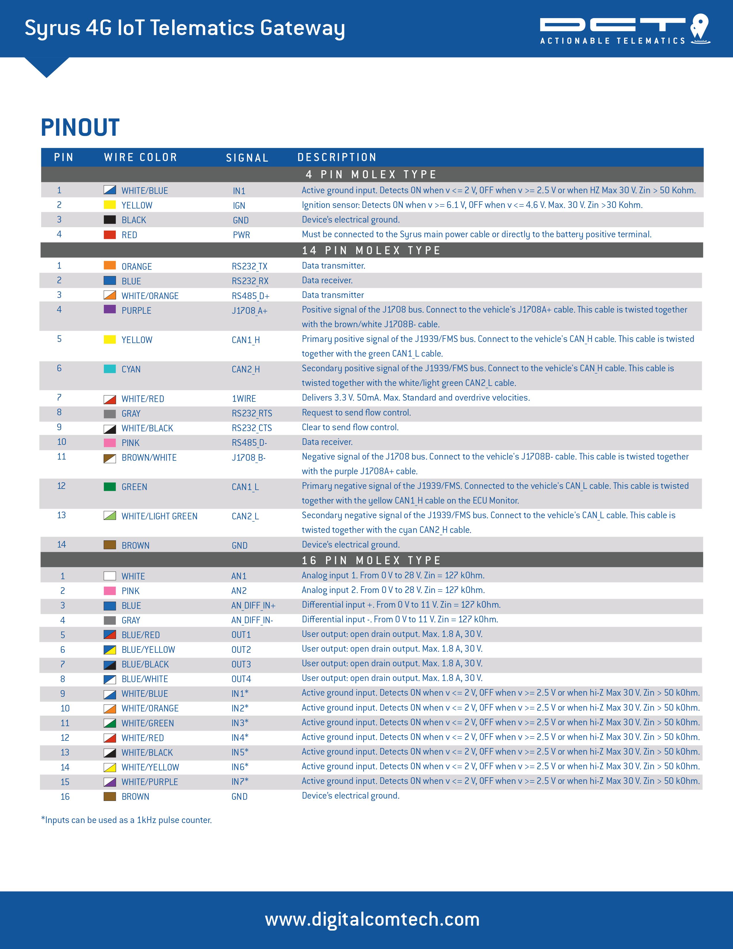
Click here to download the wiring diagram.
With the inputs you can connect the Syrus to a button or a switch and detect the state, whether active or inactive.
The outputs can be used to activate buzzers, relays, LEDs, etc.
To interact with the inputs and outputs you can use the apx-io core tool.
Analog Inputs
| PIN | Color | Signal | Description | ||
|---|---|---|---|---|---|
| 1 | WHITE | AN1 | Analog input 1. From 0V to 28V Zin = 127kΩ. | ||
| 2 | PINK | AN2 | Analog input 2. From 0V to 28V Zin = 127kΩ. | ||
| 3 | BLUE | AN_DIFF_IN+ | Differential input +. From 0V to 11V Zin = 127kΩ. | ||
| 4 | GRAY | AN_DIFF_IN- | Differential input -. From 0V to 11V Zin = 127kΩ. | ||
Syrus 4G comes with two differential analog inputs from 0V to 28V. These inputs have protection against voltages greater than 28V. 127 kΩ impedance.
The differential inputs pin 3 & 4, indicate the positive and negative voltage differential between both analog sensors. The range of the differential inputs are from 0-11V.
Get analog values
$ sudo apx-io getall analogs{"AN1":500,"AN2":1000,"DAN":500,"BAT":4.039}Outputs
| PIN | Color | Signal | Description | ||
|---|---|---|---|---|---|
| 5 | BLUE/RED | OUT1 | User output: open drain output. Max. 1.8A, 30V | ||
| 6 | BLUE/YELLOW | OUT2 | User output: open drain output. Max. 1.8A, 30V | ||
| 7 | BLUE/BLACK | OUT3 | User output: open drain output. Max. 1.8A, 30V | ||
| 8 | BLUE/WHITE | OUT4 | User output: open drain output. Max. 1.8A, 30V | ||
Syrus 4G has 4 discrete outputs located on the 16-pin molex-type connector. The outputs are Open-Drain type with no internal pull-up resistor. Meaning that the user has to provide a pull-up resistor to any positive voltage (30V max.) to detect an inactive output by voltage.
Each output can drive a continuous current of 1.8A. The output's over current protection will shutdown the output if it detects a current greater than 1.8A. The output restarts automatically after the over current state finishes. This can take up to 5 seconds. The short-circuit: SO1, SO2, SO3, and SO4 signals transition to True when the over current state is detected.
The outputs also have a over temperature protection of 165°C, and a ESD (Electro Static Discharge) protection.
The electrical conditions are:
| Logical State | Electrical State |
|---|---|
| Active | 0V |
| Inactive | Open or pull-up voltage (max 30V) |
If the output is used for cutting/restoring GND, a direct connection can be used.
If the output is used for cutting/restoring a positive voltage on a high current device, like for example the vehicle's ignition wire, an external device like a relay o high current transistor must be used.
Get output states
$ sudo apx-io getall outputs{"OUT1":true,"OUT2":false,"OUT3":true,"OUT4":false}Activate output 2
$ sudo apx-io set OUT2 trueInputs
| PIN | Color | Signal | Description | ||
|---|---|---|---|---|---|
| 9 | WHITE/BLUE | IN1* | Active ground input. Detects ON when V <= 2V, OFF when V >= 2.5V or when hi-Z. Max 30V Zin > 50 kΩ. | ||
| 10 | WHITE/ORANGE | IN2* | Active ground input. Detects ON when V <= 2V, OFF when V >= 2.5V or when hi-Z. Max 30V Zin > 50 kΩ. | ||
| 11 | WHITE/GREEN | IN3* | Active ground input. Detects ON when V <= 2V, OFF when V >= 2.5V or when hi-Z. Max 30V Zin > 50 kΩ. | ||
| 12 | WHITE/RED | IN4* | Active ground input. Detects ON when V <= 2V, OFF when V >= 2.5V or when hi-Z. Max 30V Zin > 50 kΩ. | ||
| 13 | WHITE/BLACK | IN5* | Active ground input. Detects ON when V <= 2V, OFF when V >= 2.5V or when hi-Z. Max 30V Zin > 50 kΩ. | ||
| 14 | WHITE/YELLOW | IN6* | Active ground input. Detects ON when V <= 2V, OFF when V >= 2.5V or when hi-Z. Max 30V Zin > 50 kΩ. | ||
| 15 | WHITE/PURPLE | IN7* | Active ground input. Detects ON when V <= 2V, OFF when V >= 2.5V or when hi-Z. Max 30V Zin > 50 kΩ. | ||
| 16 | BROWN | GND | Device electrical ground. | ||
| *Inputs can be used as a 1kHz pulse counter | |||||
| Be careful with the colors of the wires to not get it confused with the wire colors of the 14-pin molex connector. | |||||
The electrical conditions for the inputs are as follows:
| Logical State | Electrical State |
|---|---|
| Active | 0V to 2V |
| Inactive | 2.5V to 30V or Open |
A typical input configuration consists of the input connected trough a switch to GND. This makes the input float whenever the switch is open indicating that the input is Inactive, and makes the input go to 0V when the switch is close indicating that the input is Active.
Voltage detection can be used too:
- Any voltage above 2.5V will indicate that the input is Inactive
- Any voltage between 0V and 2V will indicate that the input is Active
It is normal to see a ~3.7V voltage on the Syrus inputs when nothing is connected to it. This voltage is set on purpose through a pull-up circuit (50kΩ resistors) in order to fix an inactive state when there is nothing connected to the inputs. The pull-up circuit also allows to connect an open drain or open collector output of a device directly to Syrus. The inputs are connected internally to several protection circuits, including over voltage protection among others. The maximum input voltage is 30V.
Get input states
$ sudo apx-io getall inputs{"MOT":false,"IGN":true,"IN1":false,"IN2":false,"IN3":false,"IN4":false,"IN5":false,"IN6":false,"IN7":false,"PWR":true,"SO1":false,"SO2":false,"SO3":false,"SO4":false,"TIG":false}Updated 8 months ago