CONNECT
Installation guidelines for the Syrus 4 device
This guide provides instructions on the general installation for the Syrus 4 as well as some useful tips and considerations.
Syrus can be installed for various applications under many environments, the most common being inside a vehicle as long as the following environmental conditions are met:
- No direct exposure to sun light.
- Away from excessive heat sources like the motor or the exhaust's path.
- Away from excessive cold sources like a truck's refrigerator or AC system.
- Not attached to a highly vibrating structure.
The unit's location can be such that it remains hidden. The LED indicators do not have to be visible but it is recommended to have some access to them for failure/diagnostics situations.
Power Supply
The unit's power cables should be directly connected to the vehicle's battery (12V or 24V). The unit supports an operating voltage range from 8V to 38V.
When the unit is not being used in a vehicle (e.g. lab testing) it must be powered by a 12V DC adapter that supplies a minimum current of 800mA.
Warning: The internal lithium polymer battery has an integrated automatic cut off circuit to protect against over-charge, over-current and over-discharge. After long disconnection periods, the battery may activate its over discharge protection circuit.
The unit is shipped with an unplugged battery connector to help prevent this state. Plug this connector in before connecting the main power and wait for activity indication on the green LED. It is not recommended to unplug the battery, except for seldom long storage periods.
Even though it is possible for the unit to work with no internal battery, it is recommended to always use the battery, this is to prevent any data loss or memory corruption that can be caused due to momentary external power loss.
Main Power Switch
When the vehicle has a main power switch to cut/restore the battery voltage, some recommendations have to be followed:
If the switch disconnects the positive voltage of the vehicle's battery, the Syrus can be connected before or after the switch. When connected before it will keep on receiving the vehicle's power whenever the switch is off. If it is connected after the switch, the unit will run with its optional back up battery whenever the switch is turned off.
See the following figures for a better understanding of connecting the unit when the vehicle uses a main power switch:
Power switch at positive and Syrus connected after

Power switch at positive and Syrus connected before

Power switch at negative and Syrus connected after

Ignition Detection
The electrical conditions for the ignition input are:
| State | Voltage range |
|---|---|
| Ignition ON | 6.1V to 30V |
| Ignition OFF | 0V to 4.6V or Open |
This input is designed to be connected to the ignition's key position that closes the circuit between the battery's positive voltage and the vehicle's electrical system. It should not be connected to the start position which gives energy to the vehicle's start engine as this position is ON only for a short period of time. The unit's ignition sense can be directly connected to the electrical end of this position.
The inputs are connected internally to several protection circuits, including over voltage protection among others. See the Connection Diagrams for an example of this connection.
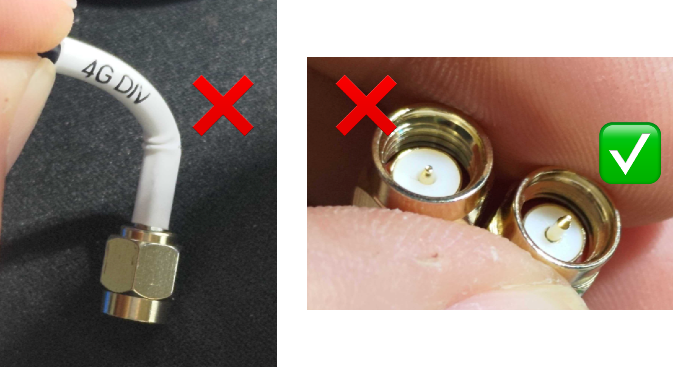
Antennas
Don't Bend Antennas During InstallationIf you bend the antenna you may lose contact as the PIN retracts. Be careful not to bend it during installation.
Connection Diagrams
Panic & Ignition Detection

Panic & Ignition Detection
Accessories
One of the most distinguishing factors of the Syrus device is it's ability to interact with many accessories at once. That said it is important to consider the amount of power drawn from all accessories you connect before proceeding to install it on a vehicle.
To help with the power consumption you can use the Power Saving Mode to make sure when the device's power is OFF for example then it goes into low power consumption mode. You should also consider cutting the power to accessories when the vehicle's Ignition is OFF for example.
Acceleration Detection
The device's internal accelerometer is oriented as follow:
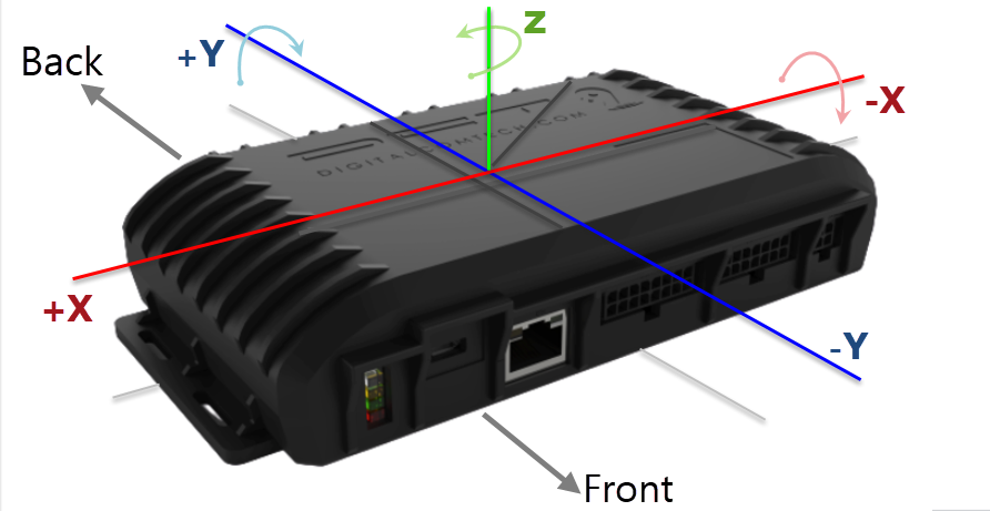
The device can be installed in any direction as long as you follow the procedure to self align the device. Self alignment and calibration of the accelerometer allows you to obtain accurate measurements for driving behavior events such as harsh acceleration, braking, cornering, etc.
Before starting the self alignment procedure consider the following:
- Syrus needs to be fitted securely in a place without vibrations, follow the guide above
- Syrus needs to have an optimal GPS signal (HDOP less than 1.5)
- Syrus needs to travel in a straight line anywhere from 500-800meters (0.3-0.5mi) with no hills
Note that some vehicles have integrated displays (Head-up displays) that can sometimes block GPS signals.
In these cases it's recommended to connect an external GNSS SMA Antenna while the calibration is performed.

Car's with smart windshields can have low GPS signal

Install an external antenna on the roof of your car for Self Alignment Procedure
Self Alignment Procedure
-
Download the mobile app Syrus Terminal Application or access the Syrus Cloud management portal
-
Access the Accelerometer section via Mobile app or Syrus Cloud
Calibration Procedure
- Make sure the Syrus is installed securely inside the vehicle
- Find an open area where the vehicle can travel in a straight line up to 500 meters
- Put the car in park and press the START button to start the alignment process
- Progress: 1% - Deleting previous alignment data
- Progress: 10% - Waiting for GNSS signal
- Progress: 30% - Running initial stage. Computing recorded data
- Progress: 50% - Running second stage. Waiting for GNSS signal
- Progress: 70% - Waiting for vehicle speed to go over 30kph
- Accelerate slowly until the car reaches 30kph, keep it at this speed for 3 seconds
- Progress: 80% - Waiting for a valid braking event
- Slow down until the speed is about 10kph then come to a sudden stop 0kph
- Progress: 90% - Braking event detected. Computing recorded data
- Once stopped stay in the same position for up to 30 seconds until the process says DONE
- Progress: 100% - Alignment process done
Once completed the configuration thresholds are auto populated. It's recommended to leave it with these calculated settings for optimum performance.
Liability and Warranty Information
Digital Communications Technologies is not liable for any issues or consequences arising from the improper installation of our devices inside vehicles. We strongly advise that you seek professional installation services to ensure the optimal performance and safety of our products. The guides and information we provide are for generic installation purposes.
Our devices are also subject to a limited warranty, please read that information here:
Devices Limited Warranty
Updated 8 months ago